As an example, if Faye has children Alia, March, and Ralph, two of whom have children, their family relationship may be described by Figure 8.1. The notation associated with such structures is fairly comfortable for anyone conversant witj both families and botany. Faye is the root node of a tree, Faye's Family. The tree rooted at Faye has three braches, and they are called subtrees. The subtree rooted at Alia has two branches, at Ralph one, and at March none. Wrye, Jan, March, and Will are leaf nodes of Faye's Family and of its substrees. All other nodes are interior nodes. Alia and Faye are both ancestors of Wrye and Jan.
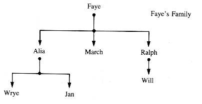
Figure 8.1
In the literature, Faye is commonly called the father of March, Alia, and Ralph, and these three are the sons of Faye. (It is perfectly acceptable to use mother and daughter, as in done for cells in biology.) Wrye and Jan are siblings, often called brothers. Faye is the grandfather of Jan.
A single node with NIL (or u) children is a tree, and so is the empty tree. Faye's Family is specifically a tree within the more general category graph. The crucial feature making it a graph is that the subtrees (subgraphs) reachable from any pair of nodes are disjoint. To generalize, the ith child of a node is the root of a tree itself. It is the ith subtree of the tree rooted at n. This is abbreviated to "the ith subtree of n."
Faye's Family can be modeled by a data structure with links representing the directed access from a node to its children. The many applications for general tree structures are limited by their own generality: the nodes of a general tree might need to have any number of links. In some applications, such as representations of family trees, it may not always be possible to foretell how many links are enough. Even if a maximum is imposed, most of the links of most nodes may be unused.
A useful compromise that contains a one-to many relationship and yet controls the proliferation of children is the binary tree. A binary tree may have a left child and a right child, which is not the same as having two children. The trees in Figure 8.2 are equivalent as trees, but not equivalent as binary tree. A binary trees T1
General trees with more than two children per node can be transformed into binary trees by the rule:
Order the children of a node 0 of tree T to obtain children c1,c2, . . .,ck. Then c1 becomes the left child of N. If N is the (i - 1)st child of a node P and there is an ith child of P, then that ith child of P becomes the right child of N.
The tree structure rooted at Faye becomes a binary tree in Figure 8.4.
Note: The distinction between binary trees and trees is important to recognize, but it is common to ignore the distinction in situations where it is not significant.
One advantage that tree-like structures have over linear linked lists is that, on the average, fewer links need to be processed to get from one node to another (assuming, of course, that the choice of which branch to take can be determined). The binary tree BT1 in Figure 8.4 has given up some of the advantage inherent in the original tree because there are more links between the root and some leaves than there were. That advantage can be regained by balancing the binary tree so that the distances from root to leaves tend to be as near the minimum as the application allows. In this particular case, rearranging the binary tree would lose the information modeled by it; for some applications, however, balancing is an advantage.
We will return to the issue of balancing in section 8.7--after examining general features of binary trees in section 8.1, their implementation in section 8.2, finding our way around them in sections 8.3 and 8.4, ordering them in section 8.5, and applying them in section 8.6. Section 8.8 exhibits one more way to walk around a tree.
Exercises E8.1 and E8.2 are appropriate at this point.
Binary trees, like the data structures introduced in previous chapters, are defined by the operators applied to them. In contrast to the previous structures, binary trees have shape; and shape is determined by the number of nodes at various distances from each other. The efficiency of management algorithms is affected by the shape of binary trees. Insertion and deletion algorithms themselves change the shape of a tree. If no operations that change shape or size are applied to a binary tree, then it is static; otherwise it is dynamic.
The efficiency of algorithms that provide access to trees is amortized by averaging over a sequence of operations. For many applications, restrictions are applied in the form of structural parameters that control shape. For static trees, these restrictions only affect the cost of searching; but, for dynamic trees subject to many insertions and deletions, shape changes are controlled by constraints defined by parameters. Shape control is introduced in the interest of increasing the amortized efficiency at the cost of more overhead during individual uses of the algorithms.
The nature of the structure BINARY TREE is determined by the operations applied to it. Binary trees can be empty, and they remain empty until a node is added to them; and so their locator, root, has an appropriate initial value: NIL or u (or zero for array implementations). The genesis of a binary tree is an operation formally called CREATE.
Deletions from a binary tree can remove all of its nodes, and so root may be dynamically set to NIL or u (or zero for an array implementation). The formal name of the operation that checks the viability of a binary tree is EMPTY.
A node may be inserted into a binary tree at any link that is NIL. Such a node (any node!) is itself the root node of a binary tree. If the attached binary tree is a singleton, it becomes a leaf node. The formal operation involved is INSERT, but the question of where to insert depends heavily on the application. INSERT can be universal only if it inserts a subtree as a given child of a given node, replacing whatever was there.
The left child or right child of a given node may be set to NIL, which detaches the binary tree rooted at that child and hence partitions the binary tree into two binary trees. Note that--like attachment--partitioning deals with a subtree, not necessarily a single node. Deletion of a single node, like insertion of a single node, is application-dependent and of considerable interest in the management of binary trees.
In distinction from stacks and queues, all nodes of a binary tree are accessible by following links from the root node. The ways a binary tree can be systematically traversed to visit every node are treated in sections 8.3 and 8.4. In many applications information is available to make a choice at each node; there is a guide to following a link to the left or to the right. When this is possible, the process of locating a node can be much faster than for a general traverse. The efficiency of this guided branching is one major advantage of trees over both linear structures and more general structures (such as graphs).
Because every node in a binary tree can be located, values can be retrieved from and assigned to every node. These operations do not change the structure, they update it.
In practice, a procedure that manages a binary tree revolves about location, whether for attachment and detachment of nodes or for retrieval and assignment of values. Location, in turn, is tied to the concept of the level of the nodes in a binary tree. Briefly:
The root of a binary tree is at level zero and a child of a node is at the next higher level. The depth of a binary tree is the maximum level of any node.
For example, in BT1,
Faye is at level 0.
Alia is at level 1.
Wrye and March are at level 2.
Jan and Ralph are at level 3.
Will is at level 4.
The particular binary tree BT1 is structured to retain the family relationships of Faye's Family; but, if that is disregarded, the same names may be rearranged in a binary tree in a more compact shape, as shown in Figure 8.5.
The maximum number of nodes at level 0 in a binary tree is 1, at level 1 is 2, at level 2 is 2 x 2 = 4, and so on. In general:
There are no more than 2L nodes at level L in a binary tree.
There are no more than 2d+1 - 1 nodes in a binary tree of depth d.
(Both results can be proved by easy induction arguments.)
When the empty (NIL or u) nodes of a binary tree are included, it becomes an extended binary tree; the nonempty nodes are called internal nodes, and the empty nodes are called external nodes. The binary tree in Figure 8.6 uses u for empty, and hence external, nodes.
Note: N is an internal node BT3; but, if the external nodes are removed, N is not an interior node--it is a leaf node.
Every time a new internal node replaces an external node, it increases both the number of internal nodes and the number of external nodes by 1. Hence, by induction, a binary tree with n internal nodes has n + 1 external nodes.
The internal path length, IPL, of a binary tree is the sum of the levels of all of the internal nodes: IPL(BT3) = 7, and could be minimized to 6 by moving "N" to level 2.
The external path length (EPL) of a binary tree is the sum of the levels of all of the external nodes: EPL(BT3) = 17. If "N" were moved up to level 2, EPL(BT3) would decrease to 16.
The averages of the internal and external path lengths provide a measure of the average number of links needed to reach nodes during searches from the root. For BT3 these are:
A binary tree is full if, when it is extended, each internal node is either a leaf or has two internal descendents, not one. A binary tree is complete if all leaf nodes lie on the lowest levels and those on the bottom level are as far left as possible. Figure 8.7 shows an example of each. A complete binary tree has minimal depth for the number of nodes it contains.
Binary tree BT4 is full but not complete, and BT5 is complete.
If there are N nodes in a binary tree of minimal depth, then the path from the root to a leaf has no more than INT(ln N) links. The potential minimal cost of a search for a node is that of a binary search. In practice, the information required to know which way to branch at a node during a search is incorporated into the shape of the binary tree and tends to increase its depth.
Exercise E8.3 and problem P8.1 are appropriate at this point.
The two binary trees in Figure 8.8 are both constructed so that their node values can be retrieved in nondecreasing order with the same standard algorithm (InOrder; see section 8.3):
The location of the value 2 by a standard search algorithm (BSTT; see section 8.5.1) applied to BT7 takes a third as many link-hops as it does for BT6. If the values in these trees were arranged at random, the expected number of hops would be intermediate between these extremes. An insertion algorithm guaranteed to produce a more efficient binary tree form is itself less efficient than one that simply builds a tree suitable for searching. The compromise between forcing the shape of a binary tree and losing the speed of location within it is a central issue in section 8.7.
Trees are a naturally occurring pattern that can be modeled closely by data structures. Their fundamental feature is branching. Branching is an essential part of language and thought--of any conceptual framework that involves choices. The binary tree reduces branching to its most elementary form, two-way branching. Each branch that is taken in a binary tree also represents a branch that is not taken and sharpens the focus of attention. A sequence of branches sharpens exponentially, much like binary search.
The data structure BINARY TREE is a decision tool, a separator of subsets. Ways to exhaustively traverse a binary tree are useful and sometimes necessary, but in many major applications nodes are reached by relatively short sequences of branches. BINARY TREE provides guided access to an arbitrary node in the structure. It is the data structure of choice when such guidance can be built into the structure.
When binary trees are implemented with pointer-linked nodes, the nodes are constructed with three fields:
The Value field can, of course, be complex and include pointers to more data of interest. It is not uncommon for binary trees to be exogenous--to be used as directories to information stored elsewhere. This approach is particularly useful when the directory is small enough to place in the main memory of a computing system, but the data is not and resides on a disk or other peripheral storage. Sometimes the value of interior nodes are used simply to locate an appropriate leaf node that is a guide to the information of interest.
A binary tree rooted at node btLeft is linked as the left child of a node bt simply by bt
8.2.1 Array Support and the Heapform
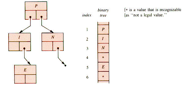
A binary tree can be supported with arrays in several ways. One way is to use two separate arrays for links and one for values. The 0th cell of one of the link-arrays can be used as a pointer to the root. The link array Left is used for this purpose in Figure 8.10.
A binary tree may be implemented in a single array A[0 . . Max] in such a way that no explicit links are needed:
The left child of node A[i] is A[2i].
The right child of node A[i] is A[2i + 1].
With this scheme, called heapform, the example above is stored as:
Note that Max must allow enough room for the rightmost leaf of the structure.
When a complete binary tree of n nodes is stored in an array in heapform, it occupies the span [1 . . n], a very compact, convenient, and efficient arrangement.
When an order condition is imposed on the placement of values within the binary tree, the result is a heap, a structure that merits a separate discussion in section 8.6.
Exercise E8.4 and problem P8.2 are appropriate at this point.
Three kinds of operations are required to visit and process the nodes of a binary tree:
a move to the left child
a move to the right child
processing a node in some manner
It can be advantageous to process a node when:
It is first reached.
Its left child (subtree) has been processed.
Its right child (subtree) has been processed.
It is possible to mix these six things in a number of ways, but two conventions are used to reduce the number of possibilities:
The left subtree of a node is visited before its right subtree.
A node is processed only once during a traverse.
Three standard traverses remain when these conventions are applied. In recursive form, they are:
These may be combined into one:
Consider the binary tree shown in Figure 8.11. Any traverse visits A (and processes it or not), then B (and processes it or not), then C, then B again, and so on. Each node is visited three times and processed on (at least) one of its visits.
The visitation sequence of example BT8 is:
The three standard traverses select the first, second, or third visit to a node in the visitation sequence for processing. Suppose, for example, that PROCESSi is simply a display of the node value. Then traverses of BT8 produce:
Program PG8.1 is appropriate at this point.
The display of a binary tree presents a fundamental problem: one of any great size will not fit comfortably within a screen or print-page. That problem can be resolved by the recursive nature of trees: display a tree of modest size where the leaf nodes identify subtrees, then display the subtrees separately.
Whether to display levels on separate lines or turn the tree sideways so that levels run right to left is a design decision. For a binary tree formed from B-I-G-S-H-A-D-E, the two options, without frills, are shown in Figure 8.12.
Display 2 is an application of the "breadth-first" traverse of section 8.4.3. (The values are displaced from the center of the display-line by an amount determined by their depth. There must be enough spread to accommodate the bottom line, which may have 2d items in a tree of depth d.)
Display 1 can be done with a recursive traverse that violates the left-first rule. The version that follows prints a string that includes the node value and prints blank spaces or the node value at each level. It is initially called with d = 0:
As indicated by their names, the standard traverses are related to the common forms of display for arithmetic expressions.
If the interior nodes of a binary tree correspond to binary operations and the leaf nodes to their operands, it is an arithmetic-expression tree. For example, suppose that A, B, and D in BT8 (section 8.3) are replaced by /, *, and +, respectively, as shown in Figure 8.13.
The postorder traverse of BT9 produces
which, when the usual precedence is applied, represents the postfix form of the infix expression:
A compiler often reverses this process, although the binary tree may not be explicitly constructed [AHO, 1977].
The preorder traverse produces:
the prefix form of the same expression. If we think of an operation as adding left and right parentheses around its results, the inorder traverse of BT9 produces:
To be sure, producing an expression with correct precedence requires either additional processing or additional (parenthesis) nodes, but the order of the tokens is that of the infix expression. The parenthesized expression can be generated by processing an operation node three times: on contact, display "("; on return from the left subchild, display the operation; and on return from the right child, display ")".
Exercise E8.5 and problem P8.3 are appropriate at this point.
One fundamental tool that can be applied to a binary tree is a procedure to make a copy of it. The recursive version is particularly apt, because it only requires that a copy be made of both the left and right subtrees and that they be joined:
The recursive forms of tree walks (traverses) are quite elegant, but they can be costly to use because extensive stacks are formed when they are executed. Recursive traversal obscures a salient fact: the links of a binary tree are directional. When a traverse is at node p, the links of p lead to its children, but not to its parent. Some way is needed to backtrack to previously visited nodes while an iterative traverse is in progress.
Explicit backtracking is usually done by stacking node pointers (indices in an array implementation) and then unstacking them to make a return. Explicitly programmed stacks contain only the necessary pointers, whereas a recursive routine is compiled so that the entire routine can be reentered. Additional information is stacked to make that possible.
A binary tree can be traversed by stacking each node when it is first encountered, and then again just prior to traversing each of its subtrees. Each node is then stacked and unstacked three times. The order of stacking is arranged so that when a subtree traverse is complete, the parent node will be unstacked next. Some way is needed to distinguish between three encounters with a node during the traverse: the initial contact and two subtree returns. Processing at these three encounters corresponds precisely to preorder, inorder, and postorder processing. All three processing modes can be combined in one algorithm, or done with walks tuned for them individually.
For the algorithm that follows, nodes of a tree structure are assumed to contain an integer field, Visit, which counts the encounters of the walk with the node:
The Visit field of each node is assumed to contain 1 at the beginning of the walk and is left that way on exit. An explicit stack, NodeStack, replaces the implicit stack of the recursive procedures. NodeStack is a stack in which the Key field of a node contains a pointer to a tree node. NodeStack may be implemented with records, but it is less obtrusive to think of it as array-based so that Pop and Push take tree node pointers as arguments without the need to encase those pointers in stack nodes.
BTT can be used as a preorder listing procedure by setting processes 2 and 3 to and using PROCESS1 as a display. The operation of the stack during such a walk can be traced by indicating a snapshot of it each time endcase is reached. For a preorder treewalk on BT8:
This causes more stack activity than would a tree-walk algorithm with a planned restriction to preorder processing.
Problems P8.4 and P8.5 and program PG8.2 are appropriate at this point.
BTT works the stack heavily: every node is popped from it three times. A quite different approach is based on the statement:
A tree walk is made by stepping left as far as possible, then taking a step to the right.
For the preorder display, the form is:
The corresponding inorder walk is derived from PreStack simply by moving the processing position. The adaptation of this kind of walk to postorder processing involves reintroducing a Visit, although only two values are required. Because only two values are required for Visit, in an array implementation the (integer) pointers may simply be negated to indicate a previously visited node.
Exercises E8.6 and E8.7 are appropriate at this point.
The binary tree traverses of sections 8.3, 8.4.1, and 8.4.2 all move from the root of a tree first to the deepest level of the leftmost path or the rightmost path (in SideView), then move to siblings on the same level. This is called depth-first traversal. An alternate class of traverses that may be applied to trees in general as well as binary trees is a breadth-first traversal.
With the help of a queue, Q, and the queue operations applicable to it, InsertRear and DeleteFront, it is possible to process nodes in the order of their levels, left-to-right within each level.
A node p of Q consists of a pointer p
The level order traverse is then:
When PROCESS(t) is a display routine, LevelOrder is the basis of a top-down display of a binary tree, in contrast to the sideways display of SideView (section 8.3.1). A display of this kind requires that the queue nodes contain information about both horizontal and vertical positioning. It is an interesting but reasonable challenge to adapt LevelOrder to that task.
Program PG8.3 is appropriate at this time.
The traversal of LevelOrder technique is generalized to use a priority queue and applied to graph structures in Chapter 10.
A given subtree, st, may easily be inserted as the left or right subtree of a given node, p, if the old subtree can be dispensed with:
Applying these statements with st = NIL removes a subtree without regard to what it contains. Thus, the fundamental issue in most applications is what to do with the other nodes of a subtree when a single node p is added or deleted at its root. Both subtrees of p cannot be used as direct replacements for p when it is deleted, and so decisions about what to do with a subtree involve the relationship of the subtree nodes to the rest of the structure. Such relationships generally exhibit some structural parameter, a restriction on the placement of nodes in the binary tree. In particular, binary trees may be ordered.
A binary tree bt may be constructed so that it has property order:
If p is any node of bt, no node in the left subtree (rooted at p
DEFINITION: A binary tree with property order is a binary search tree (BST).
8.5.1 A Binary Search Tree Traverse: BSTT
8.5.2 Insertion and Deletion in a BST
8.5.3 Static Tree Files (optional)
BT10 in Figure 8.14 is a BST but would not be one if the value 15 were replaced by 25 because the defining condition would be violated for the root node.
Note that an inorder traverse of BT10 returns the values in the defining order. (This statement can be used as a definition of a BST.) The creation of a BST is thus a sorting method. Without control of the depth of the tree, it is an O(n2) procedure.
The values of a BST do not, of course, need to be numeric. Any operator that has the mathematical property of transitivity (A.op.B and B.op.C implies A.op.C), together with the values on which it operates, will do for the formation of a BST.)
The traverse of a BST is greatly simplified because no backtracking is required--the order property guides a search directly to the appropriate node (which may be external). It is:
In a BST, the insertion and deletion of nodes must be done in a way that maintains the structural parameter order. Insertion replaces an external node of the extended tree and only involves finding the appropriate parent and which child of the parent the inserted node is to become. Deletion may be of an interior node and involve shifting subtrees. The first task of either is to determine where in the binary tree a node belongs and if that spot is occupied.
Three possibilities need to be determined:
The value is already in the BST.
The value is (or would become) the left child of node Pred (if inserted).
The value is (or would become) the right child of a node Pred (if inserted).
The procedure given here finds the value v in the binary search tree bt. It returns pointer p to the node in bt with value v, the predecessor Pred of p, and a signal Trio. Trio is zero or negative if v was found to be the value of an internal node, and positive if it was not found. Zero values of Trio can occur in two ways: when bt = NIL or when v was found to be the value of the root node. For a non-NIL bt,
This value is derived from BSTT by:
The resulting procedure is:
NodeSpot is O(depth) for a binary tree of n nodes because it does not need to traverse the structure. The order property allows the algorithm to dispense with backtracking.
The insertion of a non-NIL node n with NIL child links into a BST bt is then done by first invoking NodeSpot(bt,n
For some applications, it is convenient to allow the insertion of duplicate values into an ordered tree. Insertion of duplicate values is not so straightforward as InsertNode, and deletion is much more complex. For example, equal values may be inserted either randomly or consistently to the left or right, but deleting all occurrences of a value presents a problem. In any case, the resulting tree is partially ordered, not ordered.
A deletion procedure must deal with a number of cases. Problem P8.6 asks the reader to try to display all of the cases graphically. It is worthwhile to do so before reading the algorithm given here.
Problem P8.6 is appropriate at this point.
The deletion procedure reads:
Exercise E8.8 and program PG8.4 are appropriate at this point.
In a complete binary tree of up to n = 1,048,575 nodes, BSTT examines no more than 20 nodes. In contrast, a tree of size n could have depth n and require n tests during a search. If a binary tree (or any tree) is a directory to a file that is to be searched or is the file itself, the shape may be either static or dynamic. The two corresponding classes of files are managed quite differently.
A dynamic file is one that grows and shrinks and changes shape. The shape is normally controlled by maintaining balance, the topic of section 8.7. The benefits of controlling the depth of a file directory can be great, when costs are amortized over a sequence of operations, but the price for maintaining balance lies in the complexity of the insertion and deletion routines. More complex management requires more programming and debugging time and generally more overhead: more run-time with each use of the routines.
A static file is created with a shape that remains fixed. The shape of a binary tree that is the directory to a static file can then be optimized for efficient searching at the time of its creation. The optimum shape is normally determined by the keys of the file--it is data-directed.
Since the inorder traverse of a BST visits the keys in order, the creation of a BST from a collection of keys may be considered a tree sort. However, the insertion sequence determines the shape of the tree and hence the efficiency of subsequent searches. In particular, the worst that can happen with procedure InsertNode is for the input file to be already ordered! (A linear list will result.) Insertion can be designed to produce a well-balanced static BST, and such a procedure is to be found in Part II, section P.
There are static trees that cannot be balanced because their shape itself carries the information. One such static tree is a search tree for the international Morse code for telegraphy in which letters are represented by dots (short pulses) and dashes (long pulses). If dots correspond in interior nodes to "go left" and dashes to "go right" and letters are leaf nodes, Figure 8.15 shows a small portion of the search tree.
Program PG8.5 asks for the construction and use of the entire Morse code tree.
The Morse code is a cryptic form of trie (pronounced "try," not "tree"). Most tries use the sequence of letters in a character string to determine which way to branch at a node. Arrival at a leaf node completes the trace of the spelling of a key, and generally uncovers a pointer to an appropriate record. The nodes, however, necessarily have more than two children and so will be reintroduced in Chapter 9.
The Morse code trie has a property present in some search trees but not others: the links themselves implicitly encode information. In this book the term Code-Link Tree (CLT) is applied to trees with that property. When the links are associated with the digits determined by some number base, a CLT is called a radix search tree.
One way to optimize a static binary search tree involves constructing a CLT with these steps:
1. Determine the probability (relative frequency) with which each key is searched.
2. Encode the keys as a string of 0's and 1's so that the more frequently searched keys have shorter codes. Such codes are called Huffman codes.
3. Construct a CLT from the codes.
A code string of 0's and 1's then leads to a message (a key) at a leaf node.
This approach is used for decoding information that must be transmitted efficiently and for compression of text files in which the keys are characters. It is most effective when the set of search probabilities has a wide range. A discussion of Huffman codes is to be found in Part II, section Q, which uses material introduced in section 8.6.
One balance condition that was introduced in section 8.1.2 can be rephrased as:
A binary tree is complete if the nodes of every level in it except possibly the last one have two children, and the nodes of the last level are as far to the left as possible.
One specific structural parameter that determines a subset of the set of complete binary trees is stated as:
A binary tree is a heap if it is complete and if the value of each node is at least as large as the value of its children.
This subset proves to be very efficient and easy to use in many applications.
The natural way to implement a heap is in an array in heapform (see section 8.2.1), where the child of a node in A[i] is either A[2i] or A[2i + 1]. Heaps are not often implemented in linked form because maintaining the balance condition requires additional information in each node.
If a heap is accessed in specified ways, it becomes one support structure for a priority queue, discussed in section 8.6.2 and applied in Chapter 10.
The heap formed from a set of values is not unique. Faye's Family can be configured as a heap in several ways; one, shown in Figure 8.16, is formed by adding values to an initially empty heap in the order: Faye, Alia, March, Ralph, Wrye, Jan, Will.
In contrast, Figure 8.17 shows the heap when it is constructed by adding names in alphabetical order.
Exercise E8.9 and problem P8.7 are appropriate at this point.
The heap structure as explored in the remainder of this section is an endogenous heap implemented in an array A[1 . . Max] in heapform, as shown in Figure 8.18 for Alia's heap.
Note: It is either the heapform-heap or the priority queue that is usually meant by "heap."
If a heap contains k - 1 items in A[1 . . k - 1], the value in A[k] may destroy the heap condition if it is included in the structure. If it is allowed to migrate upward, the heap condition can be restored:
(This routine and those in the rest of this section are best understood by tracing an example.)
Exercise E8.10 is appropriate at this point.
A value can be inserted into the heap in A[1 . .n] (supported in A[1 . . Max]), by inserting it at A[n + 1] and reheaping with UpHeap:
The insertion of a value, which may destroy the heap condition, followed by restitution of it, is a common feature of heap operations.
The level-seeking of UpHeap can be used to heap an arbitrary array of values A[1 . . n].
The timing function of this procedure is T(n) = (n - 1) tk, where tk is the time required to execute UpHeap(k). The number of times the if-statement of UpHeap is executed can be no more than the maximum level in the heap, which is bounded by INT(1n n). Hence T(n) is 0(n 1n n).
One reason that heaps prove to be valuable in practice is the relative efficiency of heap operations.
The largest value (or smallest, or whichever value is heaped to the top) is retrieved and deleted from the heap but not the array by: switch A[1] and A[n], decrement n, and reheap.
Establishment of the heapform after this swap, however, requires that A[1] trickle down to its proper level. This downshift can be done with:
This process can be made somewhat more efficient by shifting values instead of swapping them, as is done in procedure DownHeap that follows. The kth item is shifted no farther than n with:
Now retrieval of the value with the highest priority (the top value) becomes:
A heap is created by repeated use of DownHeap, applied to A[i], for i = Half, Half - 1, . . ., 1, where Half = INT(n/2).
Exercise E8.11 is appropriate at this point.
The attempt to adapt the procedures of this section to pointer-variable form faces a fundamental difficulty: where is the attachment point for the node that is to be added to the heap next? A pointer to the current attachment point does not lead readily to the next one. A workable approach is to maintain a field in each node that contains a weight (the number of internal nodes) in the subtree rooted at the node. If the weights of the children are not equal and if the weights of the two left internal grandchildren are equal, the attachment point for insertion is to the right. Deletion involves location of the last-attached node with a test similar to the one used for insertion.
An alternate approach is to use an array-based heap of pointers to data records, with the heap nodes treated as discussed in this section. In effect, this approach forms an exogenous heap; the data records do not need to contain pointers and are not linked into a tree at all. The heap of pointers is a directory to an otherwise unstructured collection of records. It should be clear that any structure in this book can be used in a like manner.
Procedure DownHeap is easily turned into a sorting procedure of order O(n 1n n). The largest (highest-priority) item is moved to the top of the heap, because it is the child of some i and is swapped with A[i], then with A[i] for j = INT(i/2), and so on until it is exchanged with A[i]. It is removed (moved to the end of an active list) and the remainder reheaped to find the next-largest item. Repetitions locate the values in nonincreasing order:
The largest item is placed in A[n], the next largest in A[n - 1], etc.
The pointer-variable form of HeapSort adds the root node to a linear list as it is removed. In any case, HeapSort has a destructive readout in the sense that the heap is destroyed in the process.
The importance of HeapSort is that few sorting procedures are O(n 1n n). Although QuickSort is O(n 1n n) on the average, it is O(n2) in the worst case. InsertionSort, BubbleSort, and SelectionSort are all O(n2). A sorting procedure safe and suitable for large sets of data is often not encountered in programming courses that do not have data structures as a prerequisite.
Exercise E8.12 and program PG8.6 are appropriate at this point.
In a variety of applications it is desirable to rcpeatedly insert items into a set from which some optimal value (called the largest) can be extracted. (Here "largest" may refer to the item itself or a key field in a record.) An abstraction of such a structure is simply the set of operations that can be applied to it. In this sense, the structure priority queue is a set of data to which can be applied:
Create a priority queue from n items.
Insert an item.
Remove the largest item.
Replace the largest item big by v if v < big.
It can be useful to apply the following operations that are more difficult to implement efficiently:
Change the priority (size) of an item.
Delete a specified item.
Join two priority queues into one.
There are implementations in which most of these operations are O(ln n), which is one reason for applying priority queues.
Three implementations of priority queues can be based on structures introduced in previous sections:
1. An array of pointers to priority-class queues, each an instance of QUEUE--a pure queue. This implementation would likely be applied for a fixed number of classes, and most operation procedures would involve a binary search within the sorted array of k class headers. With natural algorithms, Create is O(n 1n k); Insert, Remove, and Replace are O(1n k). Change and Delete depend on a search of the individual class queues and so are O(m + 1n k), where m is the maximum size of a class queue. The operation JOIN is subject to interpretation in this context but is not likely to be as efficient as the other operations.
2. A heapform-heap. Create is O(n 1n n); Insert, Remove, and Replace are all O(1n n). Change and Delete are simply linear searches, O(n). Join consists of adding the items in heap H1 to heap H2, where n1 < n2 are their sizes. It is then O(n1 1n (n1 + n2)). A heapform-heap is the most common implementation for a priority queue.
3. A pointer-linked binary tree heap. Create is O(n 1n n). Insert and Replace are O(1n n). Change and Delete involve a binary tree search and so are O(n) at best. Delete and Remove would involve rebalancing of the binary tree if the balance condition is not relaxed. If balance is abandoned, the other operations approach O(n) instead of O(1n n). Join becomes O(m 1n n), where m = Min{n1, n2)}, n = n1 + n2, and n1 and n2 are the sizes of the heaps to be joined by insertion of the items of one heap into the other.
There are implementations other than the three above, and some can be useful:
4. The degenerate priority-class queue. This implementation has only one item in each class; it is a sorted list of items in an array.
5. A sorted linked list of items. Create is in effect InsertionSort, O(n2). Insert and Replace are O(n) but Remove is O(1). Change and Delete are essentially O(n) linear searches. Join is likely to be repeated insertion, O(m * n), where n = n1 + n2 and m = Min{n1, n2}.
6. An unsorted linked list of items. Insert becomes O(1) and hence Create is O(n). If the position of a specified item is not known, Replace and Remove are O(n) linear searches, as are Change and Delete. Join becomes a trivial O(1) operation (as are Change and Delete if a pointer to the specified item is provided).
7. An unsorted array of items. Create is not required, Insert is O(1). Replace, Remove, and Change are O(n) linear searches. Delete is an O(n) linear search followed by swapping the found item with A[n] and decrementing n. The JOIN operation is ambiguous or simply copies all of the items into some array.
Any priority queue can be used in a sorting algorithm by repeated application of Remove, but that does destroy the copy of the structure being used. This process is, of course, HeapSort for the heapform heap implementation.
A collection of items that differ in some quality used to select one of them for an application is a natural candidate for retention in a priority queue. The priority queue is the data structure that exemplifies the pair of demands: "Save this with the others . . . . Find the best one available."
For specific applications and restrictions, some of the data structures discussed in previous sections and in Chapters 9 and 10 are ideal. For the general situation where items are to be stored and retained in some order determined by their own qualities, the priority queue is the structure of choice. Above all, a priority queue is a structure of general utility and great flexibility.
Priority queues are applied to the construction of Huffman codes in Part II, section Q, and used in the general traverse of a graph in Chapter 10.
A general binary tree is of the form shown in Figure 8.19, where L and R are subtrees.
The root node may be considered as a pivot about which the binary tree it roots can be balanced or unbalanced by some criterion. Since this scheme applies at every node in a binary tree, balance is a local effect. It becomes a global effect with the restriction that a tree not be unacceptably out of balance at any node. Global balance is important for search trees because it determines the amortized cost of a sequence of searches.
Ways to measure subtrees L and R for comparison with each other that have been applied include:
height (depth)
weight (the number of external nodes)
internal path length (IPL)
Perfect balance is too much to ask because it generally is present only for complete trees, and so balance criteria are designed to optimize the balance for arbitrary trees. Insertions and deletions can change the balance at arbitrary points within a binary tree, for better or worse. When an operation changes the balance to the point that it needs to be restored, rebalance is done by rotation about a pivot node.
Suppose, for example, that the binary tree shown schematically in Figure 8.20 is balanced at n and at p, but an insertion is made into subtree R2 that causes an inbalance (by the criterion in use).
Then a single left rotation (SLR) can be used to restore balance and maintain the order condition, as shown in Figure 8.21.
As a more specific example, the effect of an SLR on the tree in Figure 8.22 helps its balance (by almost any criterion).
Sometimes a single rotation is not sufficient, and a double rotation is required, as shown in Figure 8.23.
For a specific example, a double rotation improves the balance of the tree in Figure 8.24 (by almost any criterion).
The right-rotation forms are symmetric to the left-rotations illustrated. Both single and double rotations are designed to maintain the order of the keys.
Since rotations may take place around any node in the tree, the parent of the pivot node is involved: the pivot node is either its left or its right child, and that pointer is changed. For the sake of clarity, it will be assumed that the pivot node is the root in the discussion that follows, and all the subtrees shown are non-NIL.
With these simplifying assumptions, SLR becomes:
Similarly, DLR is:
In practice, a number of special cases must be dealt with.
Several general features of binary tree balancing are of interest. Insertion is always made at a leaf node. For height- and weight-balance criteria, insertion requires no more than one rotation (if any) in order to restore balance. With IPL balance, rotations can propagate down the tree.
Deletion can always be of a node with no more than one internal child. If the search for a deletion key locates it at node p, then in the sequence of values that determines the tree, the values adjacent to p
where Pred is the node in the left subtree of p to which p would be added by an insertion. Similarly, Succ is the node in the right subtree of p to which p would be added by an insertion. Insertion always replaces an external node, which has a parent with no more than one internal child. Consequently, the p
Rotations caused by deletion can propagate up along the sequence of nodes in the search path to the deleted node. Reversing this path involves stacking the search path as it is generated, or retracing it, or building the tree with parent links in the nodes, or reversing links as the path is traced (a technique used in Part II, section M) and then restoring them.
The nodes of a balanced tree generally contain information fields that indicate the state of balance at a node. Rotation, insertion, and deletion procedures maintain the fields to reflect altered conditions.
Perhaps the easiest dynamically balanced tree structure to maintain, and one of the most often applied, is the B-tree discussed in section 9.5.
A tree structure that is reformulated as a binary tree and then balanced is the Red-Black Tree of section 9.6 and Part II, section U.
Further details about height-balanced trees, commonly called AVL trees, are to be found in section 8.7.1. Details of the management routines for them are to be found in Part II, section R. Weight-balanced trees, commonly called BB(
IPL-balanced trees are treated in [GONNET, 1983]. Their advantage is in management routines that are simpler than for AVL trees, and their disadvantage is in rotations that can propagate down the tree.
The analysis of the cost of maintenance procedures for various balance criteria, their amortization, and their relative merits lie outside the aims of this book. As pointed out elsewhere [GONNET, 1983], research is yet to be completed on some questions concerning:
the (worst case, average, or amortized worst case)
number of (rotations, node inspections)
to (search, insert, or delete)
a key in (AVL, BB(
trees.
Height-balancing was achieved by G. M. Adel'son-Vel'skii and E. M. Landis in 1962, and hence such trees are called either AVL trees or height-balanced trees.
If bt is a binary tree with subtrees L and R, then bt is height-balanced (has the AVL property) iff:
1.
2. L and R are themselves height-balanced.
The tree in Figure 8.25 fails to be height-balanced at E, and hence G, although it would be 1-balanced at G on the basis of the relative heights of its subtrees alone.
A detailed treatment of the management routines for AVL trees is to be found in Part II, section R.
Suppose that bt is an extended binary tree with left and right subtrees L and R. With the notation:
Clearly,
The parameter that measures how close to 1/2 the balance is to be maintained is
1.
2. if bt is not empty, L and R are in BB(
Clearly,
The
The details of managing BB(
Exercise E8.13 and problem P8.8 are appropriate at this point.
A binary tree can be traversed without the use of (implicit or explicit) stacks in several ways. One way is with the use of threads.
A thread is created by replacing NIL (external) links. A NIL right link is replaced with a pointer to the node that would be processed next in an inorder traverse. A NIL left link is replaced by a pointer to the node that was processed last. The leftmost left link and the rightmost right link are set to NIL.
A threaded version of BT8 is shown in Figure 8.27.
The nodes of a threaded binary tree must be designed to implement threads. The links and the threads need to be distinguished. They are distinguished in an array implementation by using negative indices tor links and in a pointer implementation by using flags:
It is convenient to initialize the flag fields to TRUE, implying that the associated fields are pointers, not threads.
An unthreaded binary tree where the nodes are of type ThreadNode can be threaded by calling Baste(bt,NIL,NIL):
Exercise E8.14 is appropriate at this point.
A traverse of a threaded tree follows the standard pattern of: "step left as far as possible, step right one link, move to the appropriate successor." When a node is reached by following a normal link, its left subtree is to be explored. If it is reached by a thread, its left subtree has already been explored. Processing of nodes can be in postorder, preorder, or in the inorder shown on the next page.
Insertion of a node into a threaded binary tree raises the question of placement--of where the insertion is to take place. Balancing and order are not related to the choice between external nodes and threads and must depend on applications. Threads have only a minor affect on the emplacement of a new leaf node. To illustrate, consider the insertion of a node q as the right child of a leaf node p in a threaded binary tree:
Adding a node as the left child of a leaf node is similar and is left as a problem.
Problem P8.9 is appropriate af this point.
Deletion of nodes from a threaded binary tree (any binary tree) depends upon shape parameters that are heavily application dependent. The crucial issue is: what should be done with the subtrees of the excised node? The possible responses to this question differ only in detail from those applied in unthreaded trees.
Program PG8.7 is appropriate at this point.
Trees in the mathematical sense of a graph without cycles are a common form, and they can be represented in a program with the structure BINARY TREE. The nodes of a binary tree have two distinguished (left and right) child nodes. Like lists, stacks, and queues, the binary tree is dynamic and may be either endogenous or exogenous.
An important feature of binary trees is that every node is accessible from the root node by following links. There are several ways to traverse a binary tree, either recursively or iteratively. One is the universal iterative binary tree traverse BTT, which allows processing a node at each of three contacts with it during the traverse. Many application algorithms can be based on BTT or on its recursive counterpart RBTT.
Traverses more specialized than BTT process a node on only one of the traverse contacts with it, the standards being: preorder, inorder, and postorder traverses. The recursive forms of these traverses are especially handy for quick application. The iterative forms of the standard traverses require explicit stacks that are less extensive than those in the corresponding recursive forms.
A breadth-first traverse uses a queue to traverse a binary tree level-by-level. When generalized, it becomes the priority-queue traverse of a graph in Chapter 10.
Reaching a sought-for node in the minimum number of steps requires that a decision to traverse either a left subtree or a right subtree be made at each node in the walk. A binary tree with nodes ordered so that node keys direct the walk efficiently is a BST (Binary Search Tree).
An array support system for binary trees called heapform is efficient and of great utility. When order and completeness are included in a binary tree supported in heapform, it is a heap. (A heap may also be supported with pointers, but not conveniently.) Heaps are a preferred support structure for priority queues, which in practice replace several of the simplified application models presented in this book. Note the layers of structure: (array and binary tree)
Heap algorithms can be assembled into HeapSort, a sorting method guaranteed to be O(n In n) in the worst case. This is the theoretical optimum.
Binary trees are heavily used as directories to (endogenous or exogenous) files and hence repeatedly searched. The cost of searches must be amortized over a sequence of operations.
For static files, the shape is determined at creation and must be optimized at that point. A general balancing insertion algorithm is to be found in Part II, section P. A highly tuned static file technique, the use of Huffman codes, is applied to file compression and decoding of messages. The algorithms are to be found in Part II, section Q.
Dynamic files change shape with the operations of insertion and deletion, and so those operations are often sophisticated in order to maintain balance. Height, weight, and internal path length are all applied to devise balance criteria. Height-balanced trees (AVL trees) are detailed in Part II, section R. A more general structure, the B-tree, is described in Chapter 9.
Binary tree traverses can be directed without stacks by replacing NIL pointers with threads that point back to appropriate ancestors, at the cost of the initial threading.
Exercises immediate applications of the text material
E8.1 Suppose that the vowels form a tree with "O" as the root, and its children are "U", "I", "A", left-to-right and "E" is the only child of "I". Restructure this tree as a binary tree by the transformation rule given in the introduction.
E8.2 How many ways are there to arrange the vowels "A", "E", "I", "O", "U" in a binary tree so that if C1 is in the left subtree of C2, then C1 < C2, and if C3 is in the right subtree of C2, C3 > C2.
E8.3 Derive the level of each node for the tree in Figure 8.28, the depth of the tree, the IPL, and the EPL. Modify the tree to find variations with the same set of keys that are full, or complete.
E8.4 Show how the vowel binary tree of E8.1 would appear in single-array and three-array form. (In the three-array form, the vowels are to be stored in alphabetical order.)
E8.5 Add parenthesis nodes to BT9 (section 8.3.2) so that the inorder trace produces the correct infix expression.
E8.6 Trace the action of procedure PreStack on BT8 by indicating the stack contents and p each time they change.
E8.7 There is a return on entrance to PostStack, but it is not required in InStack and PreStack. Why is this so?
E8.8 Trace the insertion of T-I-P into the BST of Figure 8.29, followed by deletion of E and O:
E8.9 Construct the heap H2 of section 8.6 in stages, as was done for heap H1.
E8.10 Trace procedure UpHeap of section 8.5 on the letter sequence T-R-A-S-H-D-U-M-P, applied for k = 2, 3 . . . 9.
E8.11 Trace the action of procedure DownHeap (k,n) for k = 3,2,1 on Faye's Family, initially stored in alphabetical order.
E8.12 Trace the action of HeapSort on an array containing the letter sequence of E8.10.
E8.13 Calculate the weight-balance factors for all nodes of the binary trees BT1-BT6.
E8.14 Trace the values of the parameters p, Pred, and Next in procedure Baste of section 8.8 when it is applied to BT8. Show them as they would appear on top of the stack created by recursive calls and indicate thread assignments.
Problems not immediate, but requiring no major extensions of the text material
P8.1 Develop the induction proofs of the two level-count results of section 8.1.2.
P8.2 Suppose that pointers require two bytes of storage and values require four. How much total storage is required for a binary tree of N items? Derive answers for pointers, three-array, and single-array storage.
P8.3 Derive a scheme for adding parentheses to the display of a binary tree in which interior nodes represent binary operators so that the display traverse produces the correct infix expression.
P8.4 Design a procedure that displays node values on all three contacts with a node, then prints an encounter index under the display. (See the discussion of visitation order in section 8.3 for example output.)
P8.5 Design an iterative version of function TreeCopy of section 8.3.3.
P8.6 Redesign procedures NodeSpot and InsertNode of section 8.5.2 so that values may be duplicated in a (partially) ordered binary tree.
P8.7 How many distinct heaps of Faye's Family are there?
P8.8 Design a procedure to calculate weight-balance factors for an arbitrary binary tree.
P8.9 Write the procedure that inserts node q as the left child of a leaf node p in a threaded binary tree.
Programs for trying it yourself
PG8.1 Write a program that inputs a binary tree (assumed to be correctly linked by the user) and displays the PreOrder, InOrder, and PostOrder traverses of it. (In a language that fails to support recursion, the results of section 8.4.1 are required.)
PG8.2 Repeat PG8. I with the iterative procedure BTT and display the stack at an appropriate point if requested by the user.
PG8.3 Write a program that will accept a list of values, treat them as a heapform binary tree, and display them both top-down and sideways.
PG8.4 Write a command-shell program that manages a binary search tree, allowing display, insertion, deletion, and location of values.
PG8.5 Write a program that constructs the International Morse code tree introduced in section 8.5.3 from the table below and allows users to enter a code message of dots, dashes, and separators. The output of the program is the decoded message.
PG8.6 Write a program that inputs 10 integers and sorts them with HeapSort.
PG8.7 Write a program that creates a threaded tree by accretion (but does not support deletion) and displays the new tree.

Figure 8.2
 T2 because their left children (and redundantly their right children) differ. Will may be implemented as either the left child or the right child of Ralph, giving rise to two distinct binary trees, shown in Figure 8.3.
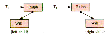
Figure 8.3
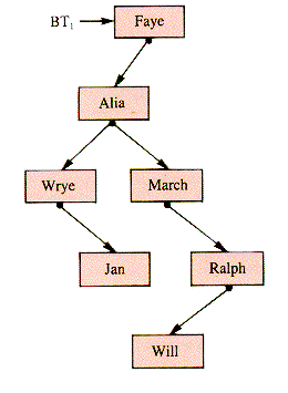
Figure 8.4
8.1 General Features of Binary Trees
8.1.1 Operations
8.1.2 Node Levels and Counts
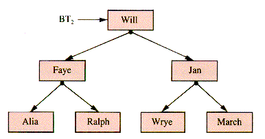
Figure 8.5
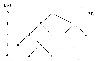
Figure 8.6


Figure 8.7
8.1.3 Shape
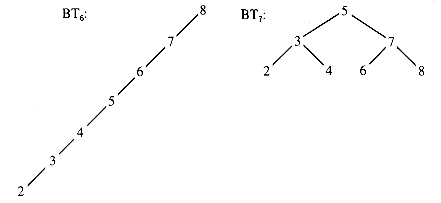
Figure 8.8
8.1.4 On the Use of Binary Trees
8.2 Implementations of Binary Trees

 .Left
.Left  btLeft, shown in Figure 8.9. Linking to a right child is similar.
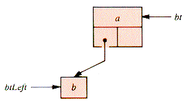
Figure 8.9
8.2.1 Array Support and the Heapform
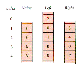
Figure 8.10
8.3 Recursive Binary Tree Traverses
procedure PreOrder(bt) OR procedure PreOrder(bt) {O(n)
if bt = NIL if bt
 NIL
NILthen return endif then PROCESS1(bt)
PROCESS1(bt) PreOrder(bt
 .Left)
PreOrder(bt
 .Left) PreOrder(bt
  .Right)
PreOrder(bt
 .Right) endif
end {PreOrder end {PreOrderprocedure InOrder(bt) {O(n)
if bt = NIL then return endif
InOrder(bt
 .Left)
PROCESS2(bt)
InOrder(bt
 .Right)
end {InOrderprocedure PostOrder(bt) {O(n)
if bt = NIL then return endif
PostOrder(bt
 .Left)
PostOrder(bt
 .Right)
PROCESS3(bt)
end {PostOrderRBTT
procedure RBTT(bt) {O(n)if bt = NIL then return endif
PROCESS1(bt)
RBTT(bt
 .Left) {Recursive Binary Tree Traverse
PROCESS2(bt)
RBTT(bt
 .Right)
PROCESS3(bt)
end {RBTT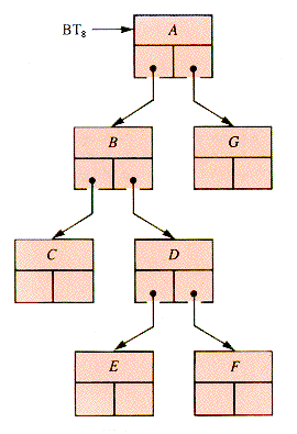
Figure 8.11
A B C C C B D E E E D F F F D B A G G G A
1 1 1 2 3 2 1 1 2 3 2 1 2 3 3 3 2 1 2 3 3
Preorder: A B C D E F G
Inorder: C B E D F A G
Postorder: C E F D B G A
8.3.1 A Recursive Tree Display
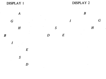
Figure 8.12
procedure SideView(d,bt) {O(n)if bt
 NIL
NILthen SideView (d + 1,bt
 .Right)
Writeln({d blank strings},bt  .Value)
SideView(d + 1,bt
 .Left)
endif
end {SideView8.3.2 Traversals of Arithmetic-Expression Trees
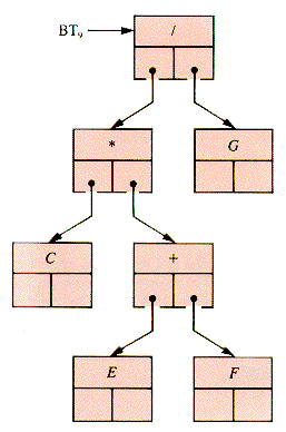
Figure 8.13
C E F + * G /
C * (E + F) / G
/ * C + E F G
((C * (E + F)) / G)
8.3.3. A Copy Procedure (optional)
function TreeCopy(bt)
if bt = NIL then return NIL endif
NEW( p)
p

 bt
bt 
p
 .Left
.Left  TreeCopy(bt
  .Left)
p
 .Right
  TreeCopy(bt
  .Right)
return p
end {TreeCopy8.4 Iterative Tree Walks
8.4.1 A General Binary Tree Walk: BTT
VisitNode = RECORD
Value : {value typeLeft :
 VisitNode
Right :
 VisitNode
Visit : INTEGER
END
BTT
procedure BTT(bt) {O(n)if bt = NIL then return endif
Push(bt)
while NOT Empty(NodeStack) do {Binary Tree Traverse Pop(p)
case of p
 .Visit
1 : PROCESS1(p) {Prefix processingp
 .Visit
 2
2Push(p)
if p
 .Left
.Left  NIL then Push (p
  .Left) endif
2 : PROCESS2(p) {Infix processingp
 .Visit
  3
3Push (p)
if p
 .Right
  NIL then Push (p
  .Right) endif
3 : PROCESS3(p) {Postfix processingp
 .Visit
  1
1endcase
endwhile
end {BTTstack output
A B A
A B C B
A B C C
A B C
A B
A B D
A B D E D
A B D E E
A B D E
A B D
A B D F
A B D F F
A B D F
A B D
A B
A
A G
A G
A G G
A
8.4.2 Individualized Iterative Tree Walks (optional)
procedure PreStack(bt) {O(n)if bt = NIL then return endif
p
 bt
btrepeat
while p
 NIL do
PROCESS1(p)
Push(p)
p
 p
p  .Left
.Leftendwhile
if Empty(NodeStack)
then return
else Pop(p)
p
 p
p  .Right
endif
forever
end {PreStackprocedure PostStack(bt) {O(n)if bt = NIL then return endif
p
 bt
btrepeat
while p
 NIL do
Push(p)
p
 p
p  .Left
.Leftendwhile
Pop(p)
while p
 .Visit = 3 do
PROCESS3(p)
p
 . Visit
  1
1if Empty(NodeStack) then return endif
Pop(p)
endwhile
p
 .Visit
  3
3Push(p)
p
 p
p  .Right
forever
end {PostStack8.4.3 A Breadth-First Traverse (optional)
 .ptr to a tree node, and a queue-link field. The insertion of a tree node t into Q in bare outline is:
procedure Insert(Q,t) {O(1)NEW(p)
p
 .ptr
.ptr  t
tInsertRear(Q,p)
end {Insertprocedure LevelOrder(BinaryTree,Q) {O(n)Insert(Q,BinaryTree)
while NOT Empty(Q) do
p
 Front(Q)
t
 p
p  .ptr
.ptrDeleteFront(Q)
PROCESS(t)
if t
 .Left
.Left  NIL
NILthen Insert(Q,t
 .Left)
endif
if t
 .Right
  NIL
NILthen Insert(Q,t
 .Right)
endif
endwhile
end {LevelOrder8.5 Ordered Binary Trees
p
 .Left
.Left  st or p
  .Right
  st
st .Left) has a value that is as large as p
  .Value, and no node in the right subtree (rooted at p
  .Right) has a value that is as small as p
  .Value. This imposes the restriction that no value be duplicated.
8.5.1 A Binary Search Tree Traverse: BSTT
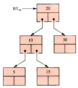
Figure 8.14
BSTT
procedure BSTT(bt,v) {O(n)PROCESS0
p
 bt {BST Traverse
while p
 NIL do
case
p
 .Value = v : PROCESSe
return
p
 .Value < v : PROCESS1
p
 p
p  .Left
.Leftp
 .Value > v : PROCESSr
p
 p
p  .Right
endcase
endwhile
PROCESSx
end {BSTT8.5.2 Insertion and Deletion in a BST
 Trio
Trio is 1 if p is the left child of Pred, and 2 if it is the right child.
PROCESS0: Trio
 0
0Pred
 NIL
NILPROCESSe: Trio
 -Trio
-TrioPROCESS1: Trio
 1
1Pred
 p
pPROCESSr: Trio
 2
2Pred
 p
pPROCESSx: NULL
procedure NodeSpot(bt,v,Trio,p,Pred) {O(depth)Pred
 NIL
NILTrio
 0
0p
 bt
btwhile p
 NIL do
if v = p
 .Value {v is an internal value and
then Trio
 -Trio {Trio will not be positive
return
endif
Pred
 p
pif v < p
 .Value
then Trio
 1
1p
 p
p  .Left
.Leftelse Trio
 2
2p
 p
p  .Right
endif
endwhile
end {NodeSpot .Value,Trio,p,Pred), followed by:
procedure InsertNode(bt,n,Pred,Trio) {0(1)if bt = NIL {create a new BST from nthen bt
 n
nreturn
endif
if Trio
 0 {v is already present. This
then return endif {could be treated as an error.if Trio = 1
then Pred
 .Left
.Left  n
nelse Pred
 .Right
  n {Trio = 2
endif
end {InsertNodeprocedure CutValue(bt,v) {O(depth)if bt = NIL
then {deal with this error.endif
NodeSpot(bt,v,Trio,p,Pred)
if Trio > 0 {v was not found in bt.then {deal with this error.endif
TackOn
 p
p  .Right {TackOn is the subtree that is
 {to replace p as a Pred child.if p
 .Left
.Left  NIL
NILthen TackOn
 p
p  .Left
.Leftif p
 .Right
  NIL
NILthen NodeSpot(p
 .Left,p
  .Right
  .Value,Top3,s,sp)
InsertNode(p
 .Left,p
  .Right,sp,Top3)
endif
endif
if Pred = NIL {the root node must go.then bt
 TackOn
else Trio
 - Trio {Specify which Pred child.
InsertNode(bt,TackOn,Pred,Trio)
endif
end {CutValue8.5.3 Static Tree Files (optional)
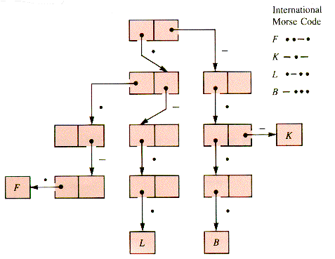
Figure 8.15
8.6 Heaps
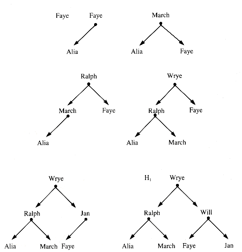
Figure 8.16
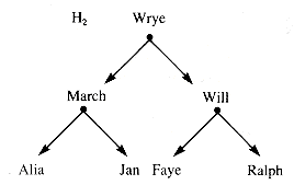
Figure 8.17
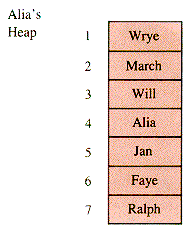
Figure 8.18
Migration
procedure UpHeap(k) {O(ln k)while k
 2 do
2 dop
 INT(k/2)
if A[k] > A[p]
then Temp
 A[k]
A[k]A[k]
 A[p]
A[p]A[p]
 Temp
Tempk
 p
pelse exit
endif
endwhile
end {UpHeapHeap Insertion
procedure InsertHeap(v) {O(1n n)if n
 Max
Maxthen {deal with this errorendif
n
 n + 1
n + 1A[n]
 v
vUpHeap(n)
end {InsertHeapHeap Creation
procedure MakeHeap {O(n ln n)for k = 2 to n do
UpHeap(k)
next k
end {MakeHeapPriority Retrieval
procedure SwapDown(k) {O(1n n)while k < n do
j
 2 * k
2 * kif j > n then exit endif
if (j < n) AND (A[j] < A[j+1])
then j
 j + 1
j + 1endif
if A[k] < A[j]
then Temp
 A[k]
A[k]A[k]
 A[j]
A[j]A[j]
 Temp
Tempendif
k
 j
jendwhile
end {SwapDownprocedure DownHeap(k,n) {O(ln n)j
 2 * k
2 * kHalf
 k
kTemp
 A[k]
A[k]while j
 n do
n doif (j < n) AND (A[j] < A[j + 1])
then j
 j + 1
j + 1endif
if Temp
 A[j]
A[j]then A[Half]
 Temp
Tempreturn
endif
A[Half]
 A[j]
A[j]Half
 j
jj
 2 * j
2 * jendwhile
A[Half]
 Temp
Tempend {DownHeapfunction DeHeap {O(ln n)Temp
 A[1]
A[1]A[I]
 A[n]
A[n]A[n]
 Temp
Tempn
 n - 1
n - 1DownHeap(1)
return A[n + 1]
end {DeHeapExogenous Heaps
8.6.1 HeapSort
procedure HeapSort(A,n) {O(n In n)Half
 INT(n/2)
for i = Half downto 1 by -1 do
DownHeap(i, n)
next i
for i = n - 1 downto 1 by -1 do
Temp
 A[i+1]
A[i+1]
 A[1]
A[1]A[1]
 Temp
TempDownHeap(1, i)
next i
end {HeapSort8.6.2 Priority Queues
8.6.3 On the Use of Priority Queues
8.7 Balanced Binary Trees
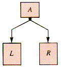
Figure 8.19
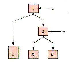
Figure 8.20
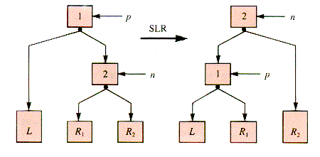
Figure 8.21

Figure 8.22
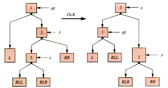
Figure 8.23

Figure 8.24
SLR: p
 .Right
  n
n  .Left
.Leftn
 .Left
.Left  p
p{switch parent-of-p pointer to nDLR: p
 .Left
.Left  n
n  .Right
gp
 .Right
  n
n  .Left
.Leftn
 .Right
  p
pn
 .Left
.Left  gp
gp{switch parent-of-gp pointer to n .Key are
Pred
 .Key < p
  .Key < Succ
  .Key
.Key .Key can be swapped with Pred
  .Key (or with Succ
  .Key if p
  Left is external), and the latter deleted.
 ) trees, are discussed in section 8.7.2.
 ), or IPL)
8.7.1 AVL Trees (optional)
 h(L) - h(R)|
  1, where h is the height function.
Figure 8.25
8.7.2 BB(
 )Trees (optional)
 T
T for the number of external nodes in tree T, the weight-balance of bt is:
 (bt) = 1/2 if bt is empty, and
otherwise
 (bt) = 1/2 implies perfect balance and it must be true that
0 <
 (bt) < 1
 . A tree is of weight-balance
  or in the set BB(
 ) if:
) if:

 (bt)
(bt)  1 -
1 -  and
and 
 1/2
1/2 ).
). = 0 is no restriction and
  = 1/2 asks for perfect balance. BB(x) is a subset of BB(y) if x
  y. It happens that if 1/3

 1/2 , then BB(
 )1/3 = BB (1/2).
 values of the nodes of a tree determine its
  -class (which it may be desirable to adjust after insertions and deletions). The nodes in Figure 8.26 have their
  value as identifier:
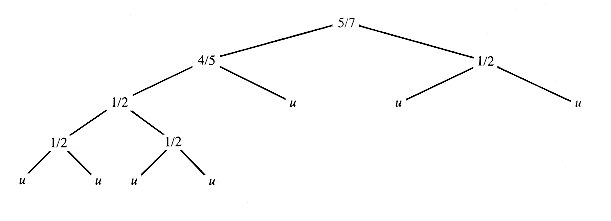
Figure 8.26
 ) trees are similar to those for AVL trees described in Part II, section R.
8.8 Threaded Binary Trees (optional)
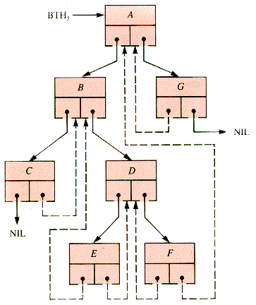
Figure 8.27
ThreadNode = RECORD
Value : {ValueTypeLeft :
 ThreadNode
Lflag : BOOLEAN
Right :
 ThreadNode
Rflag : BOOLEAN
END {ThreadNodeprocedure Baste( p,Pred,Next) {O(n)if p = NIL then return endif
if p
 .Left = NIL
then p
 .Left
.Left  Pred
Predp
 .Lflag
  FALSE
FALSEelse Baste( p
 .Left,Pred,p)
endif
if p
 .Right = NIL
then p
 .Right
  Next
Nextp
 .Rflag
  FALSE
FALSEelse Baste( p
 .Right,p,Next)
endif
end {Basteprocedure InThread(bt) {O(n)GoLeft
 TRUE
TRUEp
 bt
btwhile p
 NIL do
if GoLeft
then while p
 .Lflag do
p
 p
p  .Left
.Leftendwhile
endif
PROCESS2(p)
GoLeft
 p
p  .Rflag
p
 p
p  .Right
endwhile
end {InThreadprocedure ThreadRight(p,q)
q
 .Lflag
  FALSE
FALSEq
 .Left
.Left  p
pq
 .Rflag
  p
p  .Rflag
q
 .Right
  p
p  .Right
p
 .Right
  q
qend {ThreadRightSummary
 heapform
  heap
heap  priority queue.
Exercises
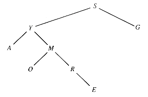
Figure 8.28
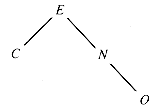
Figure 8.29
Problems
Programs
A
 - B -
- B -

 C -
C - -
- D -
D -
 E
E 
F

 -
- G --
G -- H
H 


 I
I 
 J
J  ---
---K -
 - L
- L  -
-
 M -- N -
 O ---
O ---P
 --
-- Q --
Q -- - R
- R  -
- S
S 

 T -
T -U

 - V
- V 

 - W
- W  -- X -
 - Y -
- Y - --
--Z --


