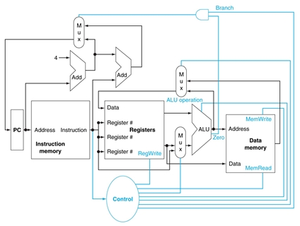
The figure at the bottom shows the basic implementation of the MIPS subset, including the necessary multiplexors and control lines.
|
- The middle multiplexor, whose output returns to the register file, is used to steer the output of the ALU or the output of the data memory for writing into the register file such as
   addi  $10, $8, 5         # $10 = $8 + 5
   lw    $t1, offset($t0)   # $t1 = mem[[$t0]+offset]
- The bottom multiplexor determines whether the second ALU input is from the registers or from the offset field of the instruction such as
   add   $8, $9, $10        # $8 = $9 + $10
   addi  $8, $9, 16         # $8 = $9 + 16
| The added control lines are straightforward and determine the operation performed at the ALU, whether the data memory should read or write, and whether the registers should perform a write operation. The control lines are shown in color. |
|
|
“We should forgive our enemies, but not before they are hanged” ― Heinrich Heine |